Camera Array Design for Digital ATC Towers at Low-Traffic Airports
Remote camera systems require custom engineering tailored to each airport's specific constraints.

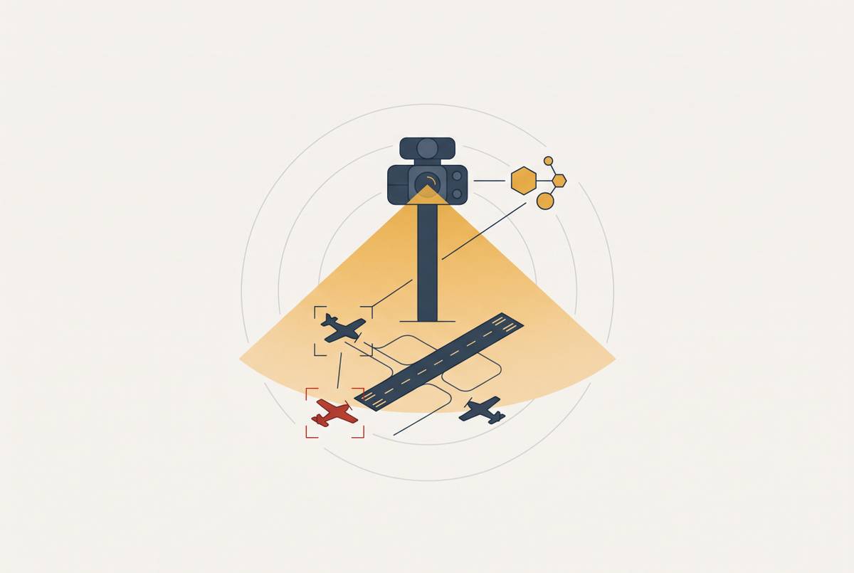
Digital ATC infrastructure at non-towered airports needs a carefully planned camera array, links to a remote control room that can be relied on, and detection and alerting that work together. Together, these layers give controllers the situational awareness they need to manage aircraft traffic where uncrewed aircraft systems and drone operations may also take place, a job that cameras alone cannot do. Camera array design for low-traffic airports is therefore a distinct engineering discipline.
Why low-traffic airports represent a distinct camera engineering problem
The defining constraint at a non-towered airport is the absence of an existing ATC service to support the new system. At a large commercial airport, cameras can augment radar, surface detection systems, and a substantial controller workforce. At a small general aviation airport, they may be the only means of giving a remote controller eyes on the field. A coverage gap therefore has a different consequence. It can remove the visual basis for service rather than merely reduce the information available to the controller.
The roughly 90% of U.S. airports operating without any control tower represent the primary candidate population for digital ATC. Yet their layouts, staffing models, weather exposure, and budgets differ enough that a standard large-airport camera plan does not transfer cleanly. In General Aviation’s work on affordable digital ATC infrastructure for uncontrolled general aviation airports, this lack of fallback infrastructure guides where cameras go and what redundancy they need. The engineering question is not how much equipment can be removed from a larger installation. It is what each airfield needs to sustain reliable observation within its own constraints.
That question begins with coverage geometry and the identification tasks within it. It then extends to visibility, hardware survival, and continuity when equipment fails. Each decision must also fit a remote operating model in which the controller is not continuously attending to that airport alone.
How coverage geometry is shaped by airport layout and traffic pattern, not camera count
A 360-degree panoramic view describes angular coverage, but it does not establish that every necessary sightline is clear. Cameras must show ground movement and the airborne traffic pattern, including the downwind, base, and final legs. Those legs may extend a mile or more beyond the field boundary. A plan centered only on the runway therefore leaves part of the operational airspace outside its design logic. Placement must begin with where aircraft move.
Obstacles make that distinction consequential. Tree lines at turf strips, terrain at mountain airfields, and hangars close to runways can interrupt otherwise broad views. A controller in a physical tower can sometimes reposition to improve a sightline, while a fixed camera cannot. The array needs a second viewpoint or an elevated mount wherever the site analysis identifies such a gap. With fewer cameras available, each placement carries more of the coverage burden.
The Winter Haven Regional Airport deployment illustrates this dependency. On-site cameras and sensors detect and track aircraft in the area and feed information to the remote facility at Bartow Executive Airport. Viable mast positions depend on the physical site, and those positions constrain the coverage that can be achieved. For affordable non-towered airport systems, including those General Aviation designs, the resulting geometry must come from a detailed site survey of runway layout, obstacles, and traffic patterns.
What resolution requirements actually mean when the camera must read a tail number at pattern distance
Once a target is within view, the next question is whether the controller can identify it. Reading tail numbers, distinguishing aircraft types, and detecting runway debris are functional requirements. These tasks are just as demanding when the airport handles fewer movements. Procurement must therefore specify what the controller needs to resolve across the operational range. An image that supports identification only close to the mast does not meet that need.
Fewer cameras can increase the resolution burden on each one. Each camera may cover a wider angular segment as it watches aircraft at different distances. An aircraft farther away then takes up less of the image, but the controller still needs to identify it. The affordable systems General Aviation develops face this same constraint, because lower camera counts do not justify a lower identification standard.
Zoom provides a useful closer view, but it is a reactive tool rather than a substitute for adequate base resolution. A controller cannot zoom into every part of the traffic pattern at once, particularly while also watching ground movement. The full field of view must therefore retain the detail needed for routine identification. Daylight and infrared performance also need separate specifications, because meeting an identification threshold in visible light does not establish that the infrared view meets it.
How infrared and low-visibility sensors change the design calculus for airports without existing weather infrastructure
Visibility affects both what a camera can show and what the controller can infer about operating conditions. Many small general aviation airports have no ATIS, no automated weather observation system, and no instrument approach procedure. The camera system consequently carries more of the burden of showing when visual conditions have deteriorated. A daylight image alone is insufficient at many such sites. Infrared capability becomes a baseline requirement.
Digital tower technology gives controllers infrared and high-definition views that can improve observation at night or in poor visibility compared with the naked-eye view from a conventional tower. Avinor’s network serving remote communities in Norway illustrates the operational setting for that capability. As of mid-2025, 14 airports were operational in a deployment planning to reach 23 airports enabled by the InNOVA ATC system. Small airports exposed to marginal weather need low-visibility observation designed into their service, rather than added after daylight coverage is complete.
The placement of infrared sensors matters as much as their inclusion. Co-locating them with daylight cameras, or placing them closely adjacent, allows controllers to switch views without losing spatial reference. If the two views cover different areas, switching sensors can create a blind spot just when the naked eye can see the least. Infrared design must therefore follow the same coverage geometry as the daylight array. That requirement also binds the sensors to the exposed mounting locations whose environmental demands the hardware must survive.
Why environmental hardening requirements at small airports often exceed those at large ones
An exposed camera mast at an unattended airport cannot rely on prompt local maintenance. Large airports have nearby staff and backup systems to deal with some equipment problems, while small airports may have neither. At Winter Haven, the remote control facility is at another airport, Bartow Executive Airport. This separation makes hardware durability part of service continuity.
Cold-climate cameras need heated enclosures suitable for their operating environment, while dusty sites call for sealed and pressurized housings. Agricultural land can expose optics to blowing particulate, and turf or gravel strips create foreign object debris risks. Coastal locations expose hardware to salt corrosion. These exposures affect different parts of the installation, so a single enclosure specification cannot stand in for the full design assessment.
Wildlife creates another practical constraint at rural airfields. Birds can nest on masts, insects can colonize enclosures, and animals can disturb ground-level equipment. Anti-perch features deter birds from nesting on masts, while protection of housings and equipment must reflect the other site risks. Regular remote health monitoring of camera status helps detect degradation before it becomes a service outage.
How redundancy must be architected when there is no fallback tower and no on-site staff
Environmental protection reduces the likelihood of failure, but it does not remove the need to operate through one. A remote controller has no tower window to use when a camera feed disappears. The design must therefore include backup cameras, backup data links, and degraded-mode procedures from the start. Designers must ask whether observation and communication remain available after a component fails. Answering it means checking what spare devices depend on as well as how many there are.
Camera redundancy requires overlapping fields of view so that a single failure does not create a blind spot. Data link redundancy needs both primary and backup paths from the airfield sensors to the remote control room. Power continuity requires uninterruptible power and backup generation at the mast site. Each of these protections covers a different kind of failure, so each is needed. An available camera is of no operational value if its image cannot reach the controller.
Path diversity is particularly important at rural sites. A primary fiber connection and a secondary wireless or satellite connection are more resilient than two connections sharing the same physical infrastructure. Budgets must also separate the coverage that must stay available for safety, such as the view of an active runway threshold, from coverage that is desirable, such as the view of remote taxiway segments during low-use hours. At the staffing level, a shared remote center makes the network part of the resilience model, but only if each airport remains reliably connected to it.
How the multi-airport controller model changes what each individual camera array must deliver
Controllers can be certified for multiple airports while controlling only one at a time. During low-traffic periods, attention rotates across the network. A passive array that shows only what the controller chooses to inspect cannot support that model adequately. The sensor suite must flag changes that matter without a controller having to watch every feed all the time.
Object tracking and movement detection let the system do this. Software built into the system can flag runway incursions, unexpected ground movement, or aircraft entering the traffic pattern without a radio call. Those alerts draw the controller’s attention to the airport before a conflict develops. Data fusion then combines camera feeds with ADS-B and radar data in a unified display, where available, rather than leaving the controller to reconcile separate views. Integration of ADS-B and multilateration into the camera display is consequently a design requirement for this operating model.
The display itself must preserve readability when an airport occupies less screen space. Camera framing and label placement must let the controller keep an eye on secondary airports while managing the primary airport. The planned Winter Haven model makes this concrete, with control testing scheduled to begin in 2026 and controllers at Bartow Executive Airport also managing activity at their own field. The array at Winter Haven must work for controllers who divide their attention this way. Its specification therefore includes what the cameras capture and how information attracts attention and remains legible.
What deliberate camera array design enables that ad hoc or scaled-down designs cannot
A site-specific array can provide capabilities beyond the view from a conventional tower cab. Infrared extends observation where the human eye is limited, zoom supports identification at distances where binoculars would be needed, and augmented reality overlays attach flight data to aircraft in the display. These gains depend on the right geometry, enough image detail, and a service that keeps running. Additional features cannot compensate for an unseen runway threshold or an unreliable connection. Deliberate design makes the capabilities work as one observation system.
David Harris, director of Johnston Regional Airport, described what he expects the system to offer. “From an effectiveness standpoint, the expectation is that it will be much more effective than a human being in a tower with a set of binoculars”. For airports with no existing ATC service, the comparison is more fundamental than improving a tower view. A well-designed array can create a structured situational awareness function where none existed. That is the practical value of making the technology affordable without weakening its functional requirements.
The architecture can also grow through additional modules and software updates rather than physical reconstruction of a concrete tower. Avinor’s network and ENAV’s deployment across 16 low-traffic Italian airports managed from Remote Tower Centers in Padua and Brindisi illustrate the shared-center approach. Its viability rests on deliberate engineering at each connected airport as well as economies at the center. For the roughly 90% of U.S. airports without a tower, that discipline helps make ATC attainable. It makes possible an affordable service that can begin with the airfield’s actual needs and expand as those needs change.